Voltage Drop Calculator For Aluminum Wire Chart
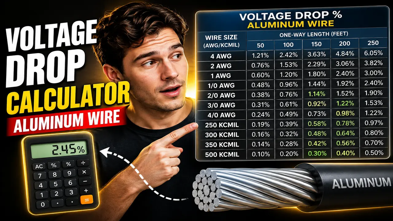
Voltage Drop Calculator For Aluminum Wire Chart estimates voltage loss, drop percentage, and load voltage from wire size, current, length, voltage, and phase.
Please complete this field to continue.
Please complete this field to continue.
Please complete this field to continue.
Please complete this field to continue.
Please complete this field to continue.
Results
Voltage Drop Calculator For Aluminum Wire Chart
TL;DR Summary
The Voltage Drop Calculator For Aluminum Wire Chart estimates voltage loss, voltage drop percentage, and voltage available at the load from aluminum wire size, current, one-way run length, system voltage, and phase. Use the result as an electrical planning estimate; privacy behavior is not specified by the supplied tool information, so avoid entering sensitive information and do not treat the result as a substitute for a complete professional electrical design.
What This Tool Does
The Voltage Drop Calculator For Aluminum Wire Chart is designed to estimate how much voltage is lost as electrical current travels through an aluminum conductor. Voltage drop matters because a long wire run, higher current, or smaller conductor can create a larger difference between the voltage at the source and the voltage available at the load.
This tool is intended for people who need a quick calculation for an aluminum conductor run. It can be useful when reviewing a proposed circuit, checking a preliminary wire-size choice, comparing conductor sizes, or understanding why a distant load may receive less voltage than the source provides. Electricians, electrical designers, contractors, maintenance personnel, students, and technically minded homeowners may find the calculation useful for preliminary planning.
The calculator asks for five inputs. First, select whether the circuit is single-phase or three-phase. Next, enter the system voltage in volts. Enter the load current in amperes, the one-way conductor run length in feet, and the aluminum conductor size. Wire sizes are provided from 14 AWG through 4/0 AWG and larger conductors expressed in kcmil.
The tool returns the estimated voltage drop in volts, the voltage drop as a percentage of the entered system voltage, and the estimated voltage remaining at the load. It also identifies whether the calculated drop is within a 3% reference level. The 3% figure is a commonly used voltage-drop design reference for branch circuits, while the NEC informational notes also discuss a 5% maximum combined feeder-and-branch-circuit voltage-drop recommendation. These are design guidance points and should not be confused with a universal maximum voltage-drop rule for every electrical installation.
Who Can Use It?
The calculator can help with early-stage electrical planning when aluminum conductors are being considered. For example, you may want to compare the expected voltage drop of 2 AWG aluminum with 1/0 aluminum on the same circuit. You can also see how a longer run or larger load current affects voltage drop.
It is especially useful for a simple circuit where the conductor size, current, voltage, phase, and one-way distance are known. It is not intended to replace a full conductor-sizing analysis. Ampacity, overcurrent protection, conductor temperature, installation method, ambient conditions, number of current-carrying conductors, terminal ratings, power factor, conductor impedance, and other design factors may also matter.
How to Use
- Step 1: Select whether the electrical system is single-phase or three-phase.
- Step 2: Enter the nominal system voltage in volts, such as 120 V, 208 V, 240 V, 277 V, or 480 V as applicable to the circuit.
- Step 3: Enter the load current in amperes. Use the current relevant to the circuit being evaluated.
- Step 4: Enter the one-way distance from the power source to the load in feet.
- Step 5: Select the aluminum conductor size from the AWG or kcmil list.
- Step 6: Review the calculated voltage drop in volts and as a percentage of the source voltage.
- Step 7: Review the estimated voltage available at the load and the 3% reference indication before making any installation decision.
Technical Explanation and Formula
The calculator uses a standard voltage-drop formula based on conductor resistance and circular-mil conductor area. For a single-phase circuit, the standard approximation is:
Voltage Drop = (2 × K × I × L) ÷ CM
For a three-phase circuit:
Voltage Drop = (1.732 × K × I × L) ÷ CM
In these formulas:
- Voltage Drop is the estimated voltage lost along the circuit, measured in volts.
- K is the conductor resistivity constant. This calculator uses 21.2 ohm-cmil/ft for aluminum at the referenced 75°C condition.
- I is load current in amperes.
- L is the one-way conductor distance in feet.
- CM is the conductor area in circular mils.
- 2 accounts for the outgoing and returning conductor path in a single-phase circuit.
- 1.732 is the approximate square root of three used for the three-phase relationship.
After voltage drop is calculated, the calculator determines the percentage using:
Voltage Drop % = (Voltage Drop ÷ System Voltage) × 100
The estimated load voltage is:
Load Voltage = System Voltage − Voltage Drop
The calculation is intentionally based on a standard conductor-resistance approximation. Actual voltage drop can depend on conductor temperature, AC resistance, reactance, power factor, installation method, conductor construction, and other circuit characteristics. Current electrical references note that conductor resistance changes with temperature and that AC impedance effects can become important for larger conductors.
Worked Example
Suppose a 208 V three-phase circuit uses 1 AWG aluminum conductors, carries 100 A, and has an 80-foot one-way run.
For 1 AWG, the conductor area is approximately 83,690 circular mils. Using the three-phase formula:
Voltage Drop = (1.732 × 21.2 × 100 × 80) ÷ 83,690
The estimated voltage drop is about 3.51 V.
The percentage voltage drop is:
(3.51 ÷ 208) × 100 ≈ 1.69%
The estimated voltage at the load is therefore about 204.49 V.
This example illustrates how conductor size, current, circuit length, and phase interact. A longer run or higher current increases calculated voltage drop. A larger conductor has more circular-mil area and generally produces less calculated resistive voltage drop.
Aluminum Wire Size Quick Reference
| Conductor Size | Conductor Area Used | Unit |
|---|---|---|
| 14 AWG | 4,110 | circular mils |
| 12 AWG | 6,530 | circular mils |
| 10 AWG | 10,380 | circular mils |
| 8 AWG | 16,510 | circular mils |
| 6 AWG | 26,240 | circular mils |
| 4 AWG | 41,740 | circular mils |
| 2 AWG | 66,360 | circular mils |
| 1 AWG | 83,690 | circular mils |
| 1/0 AWG | 105,600 | circular mils |
| 2/0 AWG | 133,100 | circular mils |
| 3/0 AWG | 167,800 | circular mils |
| 4/0 AWG | 211,600 | circular mils |
| 250 kcmil | 250,000 | circular mils |
| 500 kcmil | 500,000 | circular mils |
| 1000 kcmil | 1,000,000 | circular mils |
Why Use This Voltage Drop Calculator For Aluminum Wire Chart & How Our Calculator Beats the Competition
The practical difference between this calculator and other calculation methods is mainly the amount of setup and the level of engineering detail. The Toolhox calculator is intended for a focused voltage-drop estimate using a defined aluminum conductor size and basic circuit information. Other methods may provide more control, but they can also require more manual setup or additional engineering data.
| Method | Ease of Use | Calculation Speed | Best For | Limitations |
|---|---|---|---|---|
| Toolhox Calculator | Enter a small set of circuit inputs | Immediate calculation | Quick aluminum conductor voltage-drop estimates | Uses a standard approximation and does not perform a complete electrical design |
| Manual Calculation | Requires formula setup and conductor data | Depends on the user | Learning or checking individual calculations | More opportunity for input or arithmetic errors |
| Spreadsheet Calculation | Requires spreadsheet setup | Fast after setup | Repeated calculations and custom worksheets | Requires a correctly designed spreadsheet and maintained inputs |
| Professional Engineering Software | Usually requires more configuration | Depends on the software and model | Detailed electrical design and complex systems | More information and engineering judgment may be required |
Assumptions and Limitations
This calculator should be treated as an estimate based on a standard aluminum-conductor voltage-drop formula. It does not establish that a conductor is safe, code-compliant, correctly protected, or suitable for a particular installation.
The calculation uses a fixed aluminum resistivity constant associated with the referenced 75°C condition. Actual conductor resistance changes with temperature. AC circuits can also involve impedance and reactance, and larger conductors may require more detailed AC-resistance treatment. Installation conditions can therefore produce results that differ from a simple resistance-based estimate.
The tool also does not calculate ampacity, overcurrent protection, conduit fill, derating, terminal temperature limitations, grounding and bonding requirements, motor-specific requirements, power-factor effects, harmonics, parallel-conductor arrangements, or the complete voltage drop of multiple feeder and branch-circuit sections.
The entered length is a one-way distance. The single-phase formula accounts for the return path through its factor of two. Users should not enter the full out-and-back distance into the length field.
The 3% reference shown by the calculator is a design reference, not a universal statement that every circuit must remain below 3%. Electrical requirements can depend on the circuit, equipment, installation, adopted code, local rules, and project conditions. Current electrical design guidance describes 3% at the farthest outlet and 5% combined feeder-and-branch-circuit voltage drop as commonly referenced NEC informational-note values.
Do not rely on this result alone for a final installation decision. For a real electrical installation, verify conductor ampacity, equipment ratings, installation conditions, applicable electrical codes, manufacturer requirements, and local authority requirements. A qualified electrician or electrical engineer should review designs where safety, code compliance, equipment performance, or unusual circuit conditions are involved.