Voltage Divider Calculator With Op Amp Output Calc
Voltage Divider Calculator With Op Amp Output helps calculate divider voltage, non-inverting gain, and estimated op-amp output from resistor and input values.
Please complete this field to continue.
Please complete this field to continue.
Please complete this field to continue.
Please complete this field to continue.
Please complete this field to continue.
Results
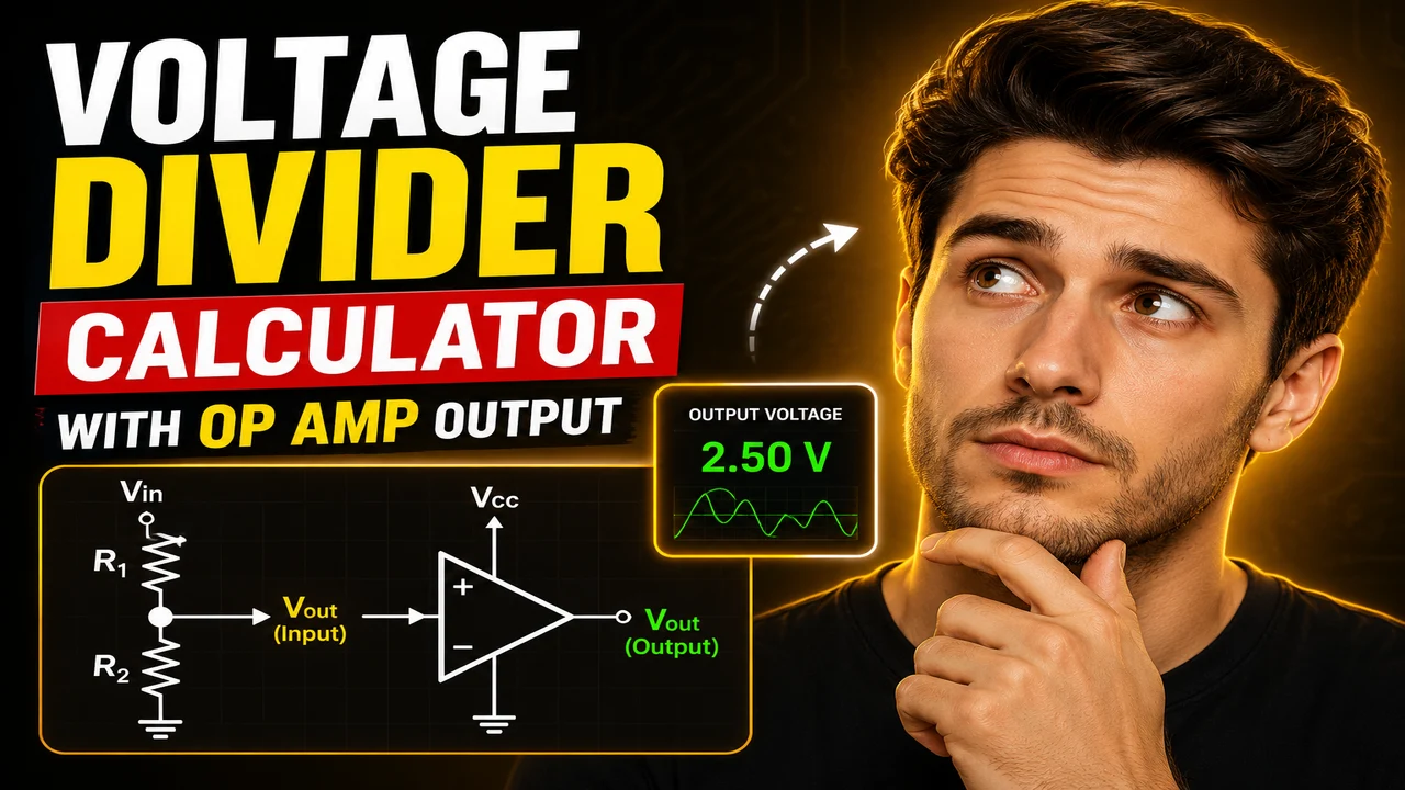
Voltage Divider Calculator With Op Amp Output
TL;DR Summary
Voltage Divider Calculator With Op Amp Output calculates the voltage produced by a two-resistor divider, the gain of a non-inverting op-amp stage, and the resulting estimated op-amp output voltage. It uses standard ideal-circuit formulas, so the result does not model every real-world op-amp limit, and the supplied tool information does not specify how entered data is stored or transmitted.
What This Tool Does
The Voltage Divider Calculator With Op Amp Output combines two common analog-circuit calculations in one workflow. First, it calculates the voltage at the center of a resistor divider. Then it applies the gain of a non-inverting operational amplifier to estimate the final output voltage.
This is useful when a circuit needs to reduce an input voltage with two resistors and then buffer or amplify that divided voltage with an op amp. It can help electronics students, hobbyists, circuit designers, technicians, and engineers check the basic voltage relationships before selecting or testing components.
The calculator uses five numerical inputs: input voltage, divider resistor R1, divider resistor R2, op-amp feedback resistor Rf, and op-amp ground resistor Rg. Voltages are entered in volts (V), while resistor values are entered in ohms (Ω). The tool returns the divider voltage, non-inverting voltage gain, estimated op-amp output, and divider ratio.
How the Voltage Divider Works
A voltage divider uses two resistors in series to produce a fraction of an input voltage. R1 is treated as the resistor connected to the input, while R2 is the resistor connected toward ground. The voltage at the divider junction is determined by the ratio of R2 to the total resistance.
This means changing either resistor changes the fraction of the input voltage appearing at the divider output. Increasing R2 relative to R1 increases the divider voltage. Increasing R1 relative to R2 decreases it.
The divider calculation assumes the divider is unloaded. In a real circuit, a device connected to the divider can draw current and change the effective resistance. An op-amp input is often modeled as having very high input impedance, which is why a voltage follower or amplifier can be used to buffer a divider. The actual circuit still depends on the selected op amp and its electrical characteristics.
How the Op-Amp Output Is Calculated
After the divider voltage is found, this tool applies the standard ideal non-inverting op-amp gain equation. The feedback resistor Rf connects from the output to the inverting input, while Rg connects from the inverting input toward the reference point, normally ground in the standard configuration.
The calculated gain is:
Gain = 1 + Rf / Rg
The estimated output is then:
Vout = Vdivider × Gain
This approach is the standard closed-loop relationship for an ideal non-inverting amplifier. Texas Instruments describes the non-inverting op-amp using a feedback divider and derives the transfer relationship from that divider, while standard electronics references give the familiar ideal gain relationship of 1 + Rf/Rg. :contentReference[oaicite:3]{index=3}
How to Use
- Step 1: Enter the source or input voltage in volts in the Input Voltage field.
- Step 2: Enter the two voltage-divider resistor values. Use R1 for the resistor connected to the input and R2 for the resistor connected toward ground.
- Step 3: Enter the op-amp feedback resistor Rf and the resistor Rg used in the non-inverting feedback network.
- Step 4: Run the calculation to obtain the divider voltage, op-amp gain, estimated output voltage, and divider ratio.
- Step 5: Compare the calculated output with the actual op-amp's supply voltage, input common-mode range, output swing, load, and other datasheet limits before building the circuit.
Technical Explanation and Formula
1. Voltage-divider formula
Vdivider = Vin × R2 / (R1 + R2)
- Vin = input voltage in volts (V)
- R1 = upper divider resistance in ohms (Ω)
- R2 = lower divider resistance in ohms (Ω)
- Vdivider = voltage at the divider junction in volts (V)
2. Non-inverting op-amp gain
Gain = 1 + Rf / Rg
- Rf = feedback resistance in ohms (Ω)
- Rg = resistance from the inverting input toward the reference point in ohms (Ω)
- Gain = voltage gain in V/V
3. Estimated output
Vout = Vdivider × Gain
The calculator does not round intermediate values before completing the calculation. The displayed results are formatted to four decimal places. The formulas are mathematical models of the stated circuit arrangement rather than a simulation of a particular op-amp device.
Worked Example
Suppose the input is 12 V, R1 is 10,000 Ω, R2 is 10,000 Ω, Rf is 10,000 Ω, and Rg is 10,000 Ω.
The divider voltage is:
Vdivider = 12 × 10,000 / (10,000 + 10,000) = 6 V
The non-inverting gain is:
Gain = 1 + 10,000 / 10,000 = 2 V/V
The estimated op-amp output is therefore:
Vout = 6 × 2 = 12 V
The divider ratio in this example is 50%. This means half of the input voltage appears at the divider junction before the op-amp gain is applied.
Quick Reference
| Value | Meaning | Unit |
|---|---|---|
| Vin | Source or input voltage | V |
| R1 | Upper voltage-divider resistor | Ω |
| R2 | Lower voltage-divider resistor | Ω |
| Rf | Op-amp feedback resistor | Ω |
| Rg | Op-amp gain-setting resistor | Ω |
| Vdivider | Voltage produced by the divider | V |
| Gain | Non-inverting voltage gain | V/V |
| Vout | Estimated op-amp output voltage | V |
Why Resistor Values Matter
The ratio of the divider resistors controls the divider voltage, but the absolute resistor values also matter in a real circuit. Very large resistor values can make a circuit more sensitive to loading, leakage, and noise. Very small values draw more current from the source.
The same principle applies to the op-amp feedback network. The gain depends on the resistor ratio, but the selected resistor values should also be suitable for the actual op amp and circuit environment.
Why Use This Voltage Divider Calculator With Op Amp Output & How Our Calculator Beats the Competition
This calculator brings the divider calculation and the standard non-inverting amplifier calculation into a single calculation flow. That makes it useful for checking the basic math without manually repeating the two formulas.
| Method | Ease of Use | Calculation Speed | Best For | Limitations |
|---|---|---|---|---|
| Toolhox Calculator | Enter the five circuit values | Immediate calculation after entry | Checking divider and ideal non-inverting output math | Does not model a specific op amp, loading, or detailed circuit behavior |
| Manual Calculation | Requires applying each formula | Depends on the person doing the math | Learning and verifying formulas by hand | More opportunity for arithmetic or setup errors |
| Spreadsheet | Requires creating or maintaining formulas | Fast after setup | Repeated calculations and custom circuit worksheets | Requires spreadsheet setup and formula management |
| Professional Engineering Software | Usually requires more circuit setup | Depends on the model and simulation | Detailed circuit analysis and simulation | More complex than a basic divider and gain calculation |
Assumptions and Limitations
This calculator uses the standard ideal voltage-divider and non-inverting op-amp equations. It assumes R1 and R2 form an unloaded divider and that the op amp operates in its linear closed-loop region.
The estimated output is not a guarantee that a physical op amp will produce exactly that voltage. Real op amps have limits related to supply voltage, output swing, input common-mode range, output current, bandwidth, slew rate, input offset voltage, bias current, resistor tolerance, and other characteristics. Texas Instruments notes that op-amp outputs can be limited by the supply rails, so a calculated output should always be checked against the selected device's datasheet. :contentReference[oaicite:4]{index=4}
The calculator also does not include a separate load-resistance model for the divider. If a connected load is not high impedance, the load can effectively appear in parallel with R2 and change the divider voltage. A buffer or suitable op-amp configuration can help isolate the divider from a load, but the actual circuit should be analyzed using the component specifications.
Do not use the result alone to approve a safety-critical, high-voltage, precision, production, or regulated circuit. For those applications, verify the design with the actual component datasheets, resistor tolerances, power ratings, supply limits, loading conditions, and appropriate engineering review.
The supplied tool information does not specify a particular op-amp model or a detailed data-storage policy. Avoid entering sensitive information, and treat the result as an engineering calculation aid rather than a substitute for circuit testing or professional review.