Solar Panel Voltage Drop Calculator For 24v System
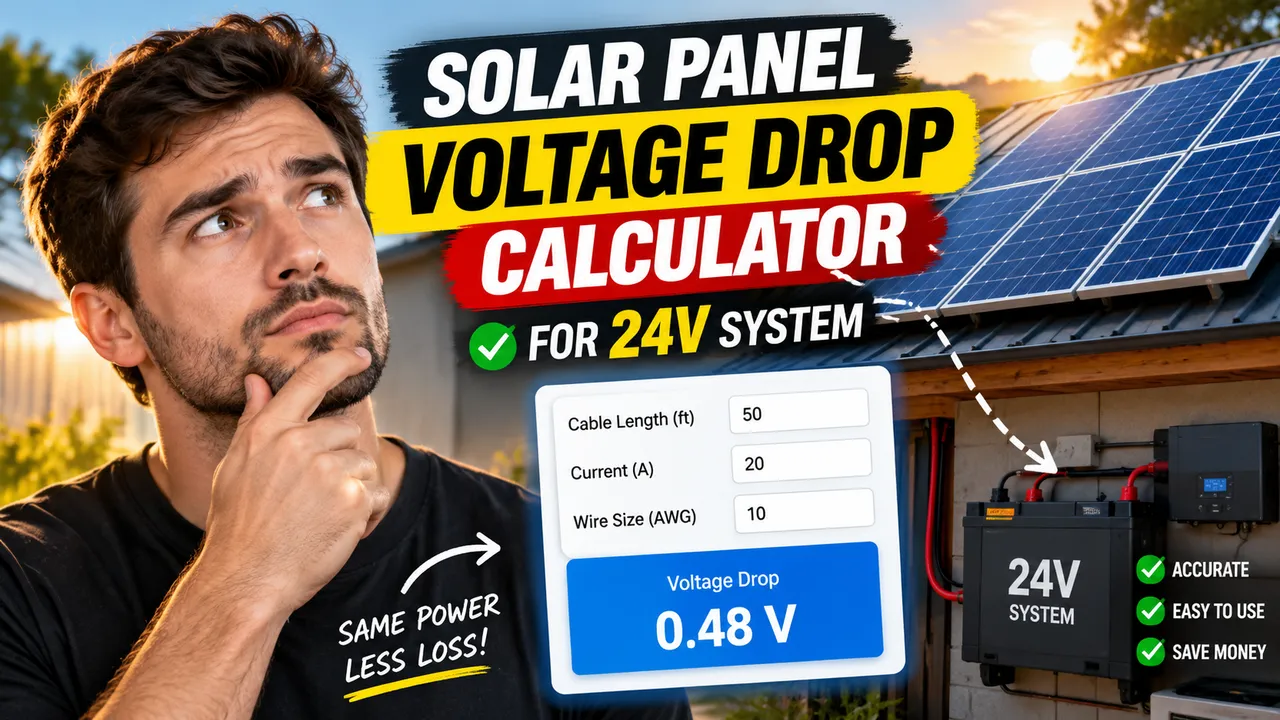
Solar Panel Voltage Drop Calculator For 24v System calculates cable loss, end voltage, and drop percentage from current, length, AWG, and temperature online.
Please complete this field to continue.
Please complete this field to continue.
Please complete this field to continue.
Please complete this field to continue.
Results
Solar Panel Voltage Drop Calculator For 24v System
TL;DR Summary
The Solar Panel Voltage Drop Calculator For 24v System estimates voltage loss in a two-wire copper DC cable run and shows the voltage drop, drop percentage, voltage remaining at the end of the cable, and a reference maximum cable length. Use it as a planning estimate rather than a substitute for complete electrical or solar-system design; the tool's privacy behavior is not specified, so avoid entering sensitive information unless the page clearly explains how submitted data is handled.
About This Tool
The Solar Panel Voltage Drop Calculator For 24v System is designed for people planning or checking a 24V solar or other low-voltage DC wiring run. Voltage drop occurs because every conductor has electrical resistance. When current travels through that resistance, some of the source voltage is lost along the cable. The effect becomes more important as current increases, the cable gets longer, or the conductor is too small for the run.
This calculator focuses on the cable voltage-drop part of the problem. It uses a fixed 24V nominal system voltage and asks for four practical values: current in amps, one-way cable length in feet, copper wire size in AWG, and estimated conductor temperature in degrees Celsius. The one-way length is important because the current travels out through one conductor and returns through another. The calculation therefore accounts for twice the entered one-way distance.
The result includes the estimated voltage drop in volts, voltage drop as a percentage of the 24V system voltage, the estimated voltage remaining at the far end of the run, total loop resistance, and a reference maximum one-way length based on a 2.5% voltage-drop target. The 2.5% figure is a planning reference rather than a universal requirement for every solar installation. Equipment instructions, applicable electrical requirements, conductor ratings, and system design conditions can require a different limit.
Who Can Use It?
The calculator can help homeowners, solar hobbyists, RV owners, off-grid users, installers, and anyone checking a 24V DC cable run. It is particularly useful when deciding whether an existing wire size is likely to create a significant voltage loss or when comparing a shorter run with a larger conductor.
For example, a 24V system carrying substantial current can experience a meaningful voltage loss even when the cable does not look especially long. Low-voltage systems are more sensitive to voltage loss because the same number of lost volts represents a larger percentage of the source voltage. Increasing conductor size or reducing cable length lowers resistance and therefore reduces voltage drop.
Inputs Used by the Calculator
| Input | Unit | Why It Matters |
|---|---|---|
| Current | A | Higher current creates greater voltage drop. |
| One-way cable length | ft | Longer cable creates more conductor resistance. |
| Copper wire size | AWG | A larger conductor has more cross-sectional area and lower resistance. |
| Estimated conductor temperature | °C | Copper resistance rises as conductor temperature increases. |
The wire-size selection uses common copper AWG sizes from 14 AWG through 4/0 AWG. The calculator does not determine whether a selected wire is safe from an ampacity, insulation, overcurrent-protection, installation-method, or code-compliance standpoint. Those are separate design questions.
How to Use
- Step 1: Enter the current in amps that you expect to flow through the 24V cable run.
- Step 2: Enter the one-way distance from the solar equipment to the receiving equipment in feet. Do not enter the round-trip distance.
- Step 3: Select the copper conductor's AWG size.
- Step 4: Enter an estimated conductor temperature in degrees Celsius. Use the expected conductor temperature rather than simply assuming that the surrounding air has the same temperature.
- Step 5: Review the voltage drop in volts and percent, the estimated voltage at the far end, loop resistance, and the reference maximum one-way length.
- Step 6: If the calculated drop is higher than your design target, consider a larger conductor or a shorter cable route and then recalculate.
Technical Explanation / Formula
The calculator treats the circuit as a two-wire DC run. The basic voltage-drop relationship is:
Voltage Drop = Current × Loop Resistance
The loop resistance is calculated from the copper resistivity, conductor length, and conductor cross-sectional area:
Rloop = 2 × ρ × L / A
Therefore:
Vdrop = I × (2 × ρ × L / A)
Where:
- Vdrop = voltage lost in the cable, in volts.
- I = current, in amps.
- ρ = copper resistivity at the estimated conductor temperature, in Ω·mm²/m.
- L = one-way cable length, converted from feet to meters.
- A = copper conductor cross-sectional area, in mm².
The calculator starts with a 20°C copper resistivity reference and applies a temperature correction using the standard copper temperature coefficient. This matters because conductor resistance increases as copper becomes hotter. The temperature adjustment is an estimate and does not model every construction, strand arrangement, installation method, or manufacturer-specific cable characteristic.
The percentage voltage drop is:
Voltage Drop % = (Voltage Drop / 24) × 100
The estimated voltage remaining at the end of the run is:
End Voltage = 24 − Voltage Drop
The calculator also estimates a maximum one-way length for a 2.5% reference target. For a 24V system, 2.5% corresponds to 0.60V:
Maximum One-Way Length = 0.60 × A / (2 × I × ρ)
This length is only a voltage-drop reference. It does not prove that a cable is properly sized for current carrying capacity, short-circuit protection, mechanical conditions, insulation temperature, connectors, or the applicable electrical installation requirements.
Worked Example
Consider a 24V system carrying 20A through 15 feet of 10 AWG copper cable one way, with an estimated conductor temperature of 60°C. Using the copper temperature correction and the two-conductor circuit calculation, the estimated voltage drop is about 2.28V. That is about 9.48% of 24V, leaving approximately 21.72V at the far end.
For the same conditions, the calculator's 2.5% reference corresponds to about 13.0 feet of maximum one-way length. This illustrates why cable length, conductor size, current, and conductor temperature should all be considered together.
Why Use This Solar Panel Voltage Drop Calculator For 24v System & How Our Calculator Beats the Competition
| Method | Ease of Use | Calculation Speed | Best For | Limitations |
|---|---|---|---|---|
| Toolhox Calculator | Enter four values and review the calculated results. | Immediate calculation after inputs are entered. | Quick 24V DC voltage-drop estimates. | Does not replace complete electrical or solar-system design. |
| Manual Calculation | Requires selecting the formula and performing the conversions. | Depends on the person doing the calculation. | Learning and checking individual calculations. | More opportunity for unit, length, or arithmetic mistakes. |
| Spreadsheet Calculation | Useful after a spreadsheet has been set up. | Fast for repeated calculations. | Projects with many cable runs or custom scenarios. | Requires building and maintaining the spreadsheet correctly. |
| Professional Engineering Software | Usually requires more setup and technical knowledge. | Can support broader engineering workflows. | Detailed system design and professional engineering analysis. | May include capabilities that are unnecessary for a simple voltage-drop estimate. |
Assumptions and Limitations
- The calculator uses a nominal 24V DC system voltage.
- The calculation assumes a two-wire copper DC circuit and accounts for both conductors.
- The entered cable length is one-way length.
- The calculation uses copper resistivity and a temperature correction rather than a manufacturer-specific cable resistance table.
- Actual cable resistance can vary with conductor construction, copper conductivity, temperature, terminations, connectors, fuses, switches, and other components in the current path.
- The calculated voltage at the far end assumes the entered current remains constant.
- The tool does not calculate wire ampacity, overcurrent protection, short-circuit performance, insulation ratings, conduit fill, thermal derating, grounding, or code compliance.
- The 2.5% reference is a planning target, not a universal legal or engineering limit.
- Solar modules do not always operate at exactly 24V. Their actual operating voltage can differ from the nominal system voltage, so this calculator should not be treated as a complete PV electrical design calculation.
- Actual solar wiring can also have resistance in connectors, fuses, switches, terminals, and other components.
For a real installation, check the equipment manufacturer's specifications and applicable electrical requirements. A qualified electrical or solar professional should review installations where voltage drop, conductor heating, protection, system reliability, or code compliance is important.