Voltage Drop Calculator For Sub Panel In Shed
Calculate feeder voltage drop for a shed sub panel with the Voltage Drop Calculator For Sub Panel In Shed. Check volts lost, drop percentage, and load voltage.
Please complete this field to continue.
Please complete this field to continue.
Please complete this field to continue.
Please complete this field to continue.
Please complete this field to continue.
Please complete this field to continue.
Results
Voltage Drop Calculator For Sub Panel In Shed
TL;DR Summary
The Voltage Drop Calculator For Sub Panel In Shed estimates how much voltage is lost along a single-phase feeder from a source panel to a shed sub panel and shows the voltage drop in volts, percentage, and estimated voltage at the shed. It is a design estimate, not a substitute for checking conductor ampacity, equipment requirements, the locally adopted electrical code, or professional electrical design; no specific privacy behavior is assumed beyond the information provided by the tool.
What This Calculator Does
A shed sub panel can be located far enough from the main panel that the feeder loses a noticeable amount of voltage before power reaches the shed. The longer the run and the higher the current, the greater the voltage drop. Conductor size and material also have a major effect.
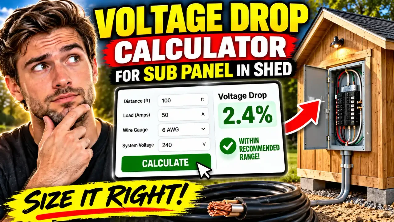
The Voltage Drop Calculator For Sub Panel In Shed is designed to estimate that feeder voltage loss for a single-phase 120 V or 240 V load. Enter the load voltage, expected load current, one-way feeder distance, conductor material, conductor size, and your desired voltage-drop target. The calculator then estimates the voltage lost in the feeder and the voltage remaining at the load.
This is useful when planning electrical service to a detached shed, workshop, garage, outbuilding, or similar structure. It can help you compare conductor sizes before installation and see why a long feeder may require a larger conductor than ampacity alone would suggest.
Who Can Use It?
Homeowners, electricians, builders, electrical designers, and people planning a detached shed can use the calculator as an initial voltage-drop check. It can also be useful for comparing copper and aluminum conductors or checking the effect of changing the feeder length or conductor size.
The calculator should not be treated as a complete sub-panel sizing tool. A voltage-drop calculation answers one question: how much voltage is expected to be lost under the selected conditions? It does not by itself establish the correct breaker, conductor ampacity, grounding and bonding arrangement, neutral size, conduit, burial depth, disconnect requirements, or other installation requirements.
Inputs You Need
- Load voltage: Choose 120 V or 240 V for the load being evaluated.
- Load current: Enter the current in amperes used for the voltage-drop calculation.
- One-way run length: Enter the distance in feet from the source panel to the shed sub panel. Do not enter the round-trip distance; the formula already accounts for the return path.
- Conductor material: Choose copper or aluminum.
- Conductor size: Select the AWG conductor size being evaluated.
- Voltage-drop target: Enter the percentage you want to use as the design comparison.
The current input should represent the load being evaluated rather than automatically assuming that the breaker rating equals the actual operating current. If the shed has several different loads, the voltage-drop calculation may need to be evaluated using the applicable design load and circuit arrangement rather than simply adding every breaker handle rating.
What the Calculator Returns
The calculator provides five main results:
- Voltage Drop: The estimated voltage lost in volts.
- Voltage Drop Percentage: The calculated loss as a percentage of the selected source voltage.
- Estimated Voltage at Shed: The source voltage minus the calculated feeder voltage drop.
- Target Voltage Drop: The number of volts represented by your selected percentage target.
- Result: Whether the calculated percentage is within or above the selected target.
How to Use
- Step 1: Select the voltage of the load you are evaluating, such as 120 V or 240 V.
- Step 2: Enter the expected load current in amperes.
- Step 3: Measure the one-way feeder distance from the source panel to the shed sub panel and enter that length in feet.
- Step 4: Select copper or aluminum for the feeder conductor material.
- Step 5: Select the AWG conductor size you want to evaluate.
- Step 6: Enter the voltage-drop target. A 3% target is commonly used for feeder design guidance.
- Step 7: Review the voltage drop, percentage, estimated voltage at the shed, and comparison with the target.
Technical Explanation and Formula
The calculator uses the standard single-phase K-factor method for an approximate conductor voltage-drop calculation:
Voltage Drop = (2 × K × I × D) ÷ CM
The variables are:
- K: Conductor resistivity constant. The calculator uses 12.9 for copper and 21.2 for aluminum.
- I: Load current in amperes.
- D: One-way conductor run length in feet.
- CM: Conductor cross-sectional area in circular mils.
The factor of 2 accounts for the two conductor paths in the single-phase voltage-drop calculation. Because of that factor, you should enter the one-way distance rather than doubling the distance yourself.
The percentage voltage drop is then calculated as:
Voltage Drop % = (Voltage Drop ÷ Source Voltage) × 100
The estimated voltage at the shed is:
Load Voltage = Source Voltage − Voltage Drop
For example, consider a 60 A load on a 240 V single-phase circuit with a 100-foot one-way run using 6 AWG copper. Using K = 12.9 and 26,240 circular mils, the estimated drop is about 5.90 V. That is about 2.46% of 240 V, leaving approximately 234.10 V at the load under the calculation assumptions.
If the same 60 A and 100-foot conditions were evaluated at 120 V, the voltage loss in volts would remain approximately 5.90 V, but the percentage would rise to about 4.92%. This illustrates why the same physical feeder can have a different percentage voltage drop depending on the operating voltage.
What the 3% Target Means
The National Electrical Code includes informational guidance that recommends designing feeders so voltage drop does not exceed 3% at the farthest outlet and that the combined feeder and branch-circuit voltage drop does not exceed 5% for the covered loads. These are informational recommendations rather than a universal standalone 3% code requirement. The applicable electrical code edition, local amendments, energy requirements, equipment instructions, and authority having jurisdiction must be checked for an actual project.
For a shed sub-panel feeder, a 3% feeder target is therefore useful as a design comparison, but it should not be presented as proof that an installation is code-compliant. The 5% figure also refers to combined feeder and branch-circuit voltage drop, so a feeder result by itself does not tell you the total voltage drop at the final outlet.
Preset Example / Quick Reference
| Scenario | Voltage | Current | One-Way Length | Conductor | Estimated Drop |
|---|---|---|---|---|---|
| Example shed feeder | 240 V | 60 A | 100 ft | 6 AWG copper | 5.90 V / 2.46% |
| Same feeder at 120 V | 120 V | 60 A | 100 ft | 6 AWG copper | 5.90 V / 4.92% |
These examples demonstrate the calculation method rather than prescribing a particular feeder size. Actual conductor selection must also satisfy applicable ampacity and installation requirements.
Why Use This Voltage Drop Calculator For Sub Panel In Shed & How Our Voltage Drop Calculator For Sub Panel In Shed Beats the Competition
| Method | Ease of Use | Calculation Speed | Best For | Limitations |
|---|---|---|---|---|
| Toolhox Calculator | Enter a small set of feeder values | Immediate calculation | Quick single-phase voltage-drop estimates | Does not replace complete electrical design or local code review |
| Manual Calculation | Requires the formula and conductor data | Depends on the person doing the calculation | Checking or learning the calculation method | More opportunity for arithmetic or input errors |
| Spreadsheet | Requires a prepared worksheet | Fast after setup | Repeated calculations and project comparisons | Requires maintaining formulas and conductor data |
| Professional Engineering Software | Usually requires more project information | Depends on the software and model | Detailed electrical system design | More complex than a focused voltage-drop estimate |
The practical advantage of a focused calculator is that it keeps the voltage-drop question separate from the larger electrical design problem. You can change the conductor size, material, distance, current, or voltage and immediately see how those variables affect the estimated feeder loss. That makes it useful during early planning and comparison.
Assumptions and Limitations
- This calculator evaluates a single-phase voltage-drop scenario.
- The formula uses the one-way run length and a factor of 2 for the circuit path.
- The K-factor method is an approximate resistance-based calculation. It does not model every AC impedance, installation, temperature, power-factor, or conductor configuration effect.
- The calculator does not perform a complete feeder ampacity calculation.
- It does not determine the correct breaker size, neutral size, equipment-grounding conductor, conduit, burial method, disconnect, or grounding and bonding arrangement.
- It does not calculate the voltage drop of downstream branch circuits. A feeder result alone therefore cannot establish the total drop to the final outlet.
- Mixed 120/240 V loads in a real sub panel may require a more detailed load and voltage-drop analysis.
- Motors, sensitive electronic equipment, nonlinear loads, and other specialized loads can require more detailed analysis.
- Local jurisdictions may adopt a particular NEC edition with amendments or additional electrical or energy-code requirements.
Use the result as an estimate and design check. For a new shed feeder, permit application, inspection, or installation involving significant loads, verify the complete design against the locally adopted electrical code and the equipment manufacturer's requirements. A qualified electrician or electrical engineer should review conditions that are outside this calculator's simplified scope.
Research basis: NFPA identifies the 2026 edition of NFPA 70 as the current NEC edition. Accessible NFPA material establishes the 3% feeder and 5% combined feeder-plus-branch guidance as informational-note guidance, while standard voltage-drop references use the single-phase K-factor method. :contentReference[oaicite:0]{index=0}