Voltage Drop Calculator For Marina Wiring
Calculate marine wiring voltage loss with Voltage Drop Calculator For Marina Wiring. Estimate voltage drop, percent loss, and load voltage from your circuit inputs.
Please complete this field to continue.
Please complete this field to continue.
Please complete this field to continue.
Please complete this field to continue.
Please complete this field to continue.
Results
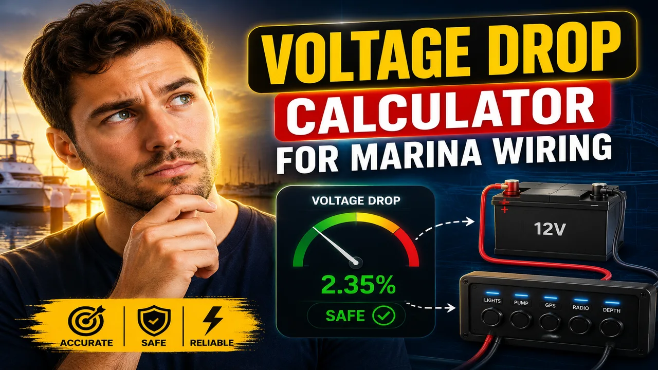
Voltage Drop Calculator For Marina Wiring
TL;DR Summary
Voltage Drop Calculator For Marina Wiring estimates voltage loss in a marine wiring circuit from the circuit voltage, load current, conductor length, conductor resistance, and allowable voltage-drop percentage. Use the result as a planning estimate rather than a complete marina electrical design or code-compliance determination; the supplied tool information does not establish how entered data is stored or transmitted.
About This Tool
Voltage Drop Calculator For Marina Wiring is designed to help boat owners, marine technicians, electricians, installers, and other users estimate how much voltage may be lost as electrical current travels through a wiring run. Voltage drop is important because a load does not always receive the same voltage that exists at the power source. Resistance in the conductors causes part of the available voltage to be lost along the circuit.
The calculator uses a straightforward electrical relationship: voltage drop equals current multiplied by resistance. To estimate the resistance of the complete circuit, the tool uses the one-way conductor length entered by the user and doubles it to represent the outgoing and return paths. This approach is consistent with marine voltage-drop guidance that treats circuit length as the path from the source to the load and back.
The main inputs are nominal circuit voltage in volts, load current in amperes, one-way conductor length in feet, conductor resistance in ohms per 1,000 feet, and the allowable voltage-drop percentage. The resistance value should come from the applicable wire specification, manufacturer data, or another reliable electrical reference for the conductor being evaluated. The calculator does not automatically identify a wire's resistance from an AWG size, because conductor construction, material, temperature, and other conditions can affect resistance.
The calculator returns five useful results. First, it shows the estimated voltage drop in volts. Second, it converts that loss into a percentage of the nominal circuit voltage. Third, it estimates the voltage remaining at the load. Fourth, it calculates the maximum voltage loss represented by the allowable percentage entered by the user. Finally, it reports whether the calculated voltage drop is within the selected limit.
How to Use
- Step 1: Enter the nominal circuit voltage, such as 12 V, 24 V, or another applicable system voltage.
- Step 2: Enter the load current in amperes. Use the current expected to flow through the circuit under the condition you are evaluating.
- Step 3: Enter the one-way distance in feet from the power source to the load. The calculator automatically doubles this value to account for the complete outgoing and return circuit path.
- Step 4: Enter the conductor resistance in ohms per 1,000 feet. Use a value appropriate for the actual conductor and installation being evaluated.
- Step 5: Enter the maximum voltage-drop percentage you want to allow.
- Step 6: Review the voltage drop, percentage drop, estimated load voltage, allowable voltage loss, and final result.
- Step 7: If the calculated drop exceeds your selected limit, review the conductor size, circuit length, current, and installation conditions before making a wiring decision.
Technical Explanation and Formula
The standard voltage-drop calculation used for this tool is based on Ohm's law:
Voltage Drop = Current × Circuit Resistance
The calculator determines circuit resistance from the complete conductor path:
Circuit Resistance = (Circuit Length ÷ 1,000) × Resistance per 1,000 ft
Because the input asks for one-way length, the tool calculates:
Circuit Length = One-Way Length × 2
The percentage voltage drop is then:
Voltage Drop % = (Voltage Drop ÷ Nominal Circuit Voltage) × 100
The estimated voltage available at the load is:
Load Voltage = Nominal Circuit Voltage − Voltage Drop
For example, assume a 12 V circuit carries 10 A, the one-way conductor length is 20 ft, and conductor resistance is 1.588 ohms per 1,000 ft. The complete circuit length is 40 ft. Circuit resistance is 0.06352 ohms. The estimated voltage drop is therefore 0.6352 V, or about 5.29% of 12 V. The estimated voltage at the load is about 11.365 V.
The calculator does not round intermediate calculations. It rounds the displayed voltage results to three decimal places and the displayed percentage to two decimal places.
Marine Voltage-Drop Targets
Marine electrical references commonly distinguish between circuits where voltage drop is more important and circuits where a larger drop may be acceptable. Blue Sea Systems, citing ABYC E-11 guidance, identifies 3% voltage drop for critical marine DC circuits such as panel feeders, bilge blowers, electronics, and navigation lights, while 10% is used for certain non-critical loads. These values are useful reference points, but they are not automatically imposed by this calculator. The user enters the allowable percentage so the calculation can be adapted to the circuit being evaluated.
| Reference target | Example marine application | Purpose |
|---|---|---|
| 3% | Critical DC circuits | Limits voltage loss more tightly |
| 10% | Some non-critical DC loads | Allows a larger voltage loss where appropriate |
Preset Examples and Quick Reference
| Input | Example | Unit |
|---|---|---|
| Nominal circuit voltage | 12 | V |
| Load current | 10 | A |
| One-way conductor length | 20 | ft |
| Resistance | 1.588 | Ω/1,000 ft |
| Allowable voltage drop | 3 | % |
With those example values, the calculated drop is about 0.635 V and the percentage drop is about 5.29%. Because 5.29% is greater than the selected 3% limit, the result is outside that selected target. The estimated load voltage is about 11.365 V.
Why Voltage Drop Matters in Marina and Boat Wiring
Voltage drop becomes more noticeable as current increases, conductor length increases, or conductor resistance increases. A long run carrying a relatively high current can therefore lose a meaningful amount of voltage even when the power source itself is operating at the expected voltage.
This matters for equipment that needs a particular operating voltage. Excessive voltage loss can affect equipment operation and can also be a sign that the wiring design needs closer review. Voltage drop should therefore be considered alongside conductor ampacity, overcurrent protection, conductor temperature rating, installation conditions, connections, and the requirements that apply to the specific boat or marina installation.
Marina Wiring and U.S. Electrical Requirements
Marina installations have requirements that go beyond a simple voltage-drop calculation. NFPA 70 Article 555 covers wiring and equipment in areas including fixed or floating piers, docks, marinas, boatyards, boat basins, boathouses, yacht clubs, and related docking facilities. The current NFPA publication catalog lists a 2026 edition of NFPA 70, so the edition adopted by the authority having jurisdiction should be checked for an actual installation.
ABYC also maintains E-11, AC & DC Electrical Systems on Boats, as part of its electrical standards. ABYC published Supplement 66 in August 2026, showing that its standards continue to be updated. The calculator should therefore be treated as a calculation aid, not as a substitute for reviewing the current applicable ABYC requirements, NEC requirements, equipment instructions, and local requirements.
Why Use This Voltage Drop Calculator For Marina Wiring & How Our Calculator Beats the Competition
| Method | Ease of Use | Calculation Speed | Best For | Limitations |
|---|---|---|---|---|
| Toolhox Calculator | Enter five electrical values | Immediate calculation | Quick voltage-drop estimates | Does not replace a complete marine electrical design review |
| Manual Calculation | Requires the formula and arithmetic | Depends on manual work | Checking individual calculations | More opportunity for arithmetic or path-length errors |
| Spreadsheet | Requires setup | Fast after setup | Repeated project calculations | Requires the user to build and maintain formulas and inputs |
| Professional Engineering Software | Usually requires more setup and domain knowledge | Depends on the software and model | Detailed electrical design and engineering work | May require additional inputs, licensing, training, or project modeling |
The practical benefit of this calculator is that it keeps the voltage-drop calculation focused. It does not attempt to make every electrical design decision for the user. Instead, it provides the calculated loss and load voltage from the values entered, which can then be considered alongside the rest of the installation requirements.
Assumptions and Limitations
- The entered resistance value is assumed to represent the conductor being evaluated and its applicable operating conditions.
- The entered one-way length is doubled to represent the outgoing and return conductors.
- The calculation assumes the same current flows through the complete circuit path.
- The calculation does not automatically determine conductor resistance from wire gauge.
- The calculation does not select wire size, fuse size, breaker size, or conductor ampacity.
- The calculation does not determine whether an installation complies with NFPA 70, ABYC standards, Coast Guard requirements, or local electrical rules.
- Marina shore-power systems can involve requirements and design considerations that are not represented by a basic voltage-drop calculation.
- Actual voltage drop can be affected by conductor temperature, material, connections, terminals, splices, installation conditions, and changes in load.
- The result is an estimate based on the information entered and should not be used as the sole basis for an electrical installation decision.
For new marina wiring, shore-power work, major boat electrical modifications, or situations involving uncertain conductor data, the calculated result should be reviewed against the current applicable standards and installation requirements by an appropriately qualified electrical or marine professional.