Solar Panel Inter-Row Spacing Calculator Online
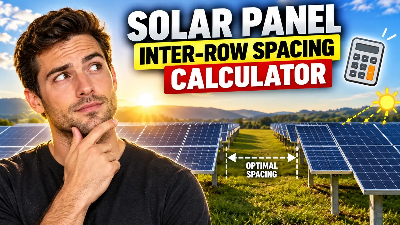
Solar Panel Inter-Row Spacing Calculator estimates row pitch and shading gap from panel length, tilt, and winter-solstice sun angle for fixed-tilt PV.
Please complete this field to continue.
Please complete this field to continue.
Please complete this field to continue.
Results
Solar Panel Inter-Row Spacing Calculator
TL;DR Summary
The Solar Panel Inter-Row Spacing Calculator estimates the clear shading gap and minimum row-to-row pitch for a fixed-tilt solar panel layout using panel length, tilt angle, and site latitude. It is a geometry-based planning estimate rather than a complete solar design study, and the supplied tool information does not establish any special privacy guarantee, so avoid entering sensitive information.
About This Tool
The Solar Panel Inter-Row Spacing Calculator helps estimate how much space should be left between rows of tilted photovoltaic panels. When solar panels are installed in multiple rows, a front row can cast a shadow onto the row behind it. The amount of space needed depends strongly on the panel's tilt, the length of the tilted panel surface, and the height of the sun above the horizon.
This calculator is intended for early-stage solar layout planning. It can be useful for homeowners, solar installers, project planners, students, engineers, and anyone who needs a quick geometric estimate of photovoltaic row spacing. It is especially useful when comparing different panel tilt angles or checking how a site's latitude affects the spacing needed to reduce inter-row shading.
The calculator asks for three values. First, enter the panel slope length. This is the distance from the lower edge of the panel to the upper edge measured along the tilted panel surface. The length field supports the calculator's length unit system. Second, enter the panel tilt angle in degrees. This is the angle between the panel surface and a horizontal plane. Third, enter the site latitude in degrees north.
The latitude input is used to estimate the solar elevation at winter-solstice solar noon. The calculator uses the standard approximation that winter-solstice solar elevation at solar noon is 90 degrees minus latitude minus approximately 23.44 degrees. This creates a simple design condition for evaluating a low winter sun angle. NREL guidance identifies the winter solstice as the design day because the sun is at a lower angle and therefore produces longer shadows. :contentReference[oaicite:2]{index=2}
The calculator produces several useful results. It shows the estimated winter-solstice solar elevation, the vertical rise of the tilted panel, the clear shading gap behind the row, and the minimum row-to-row pitch. The pitch represents the panel's horizontal ground footprint plus the calculated shadow distance. Keeping these two concepts separate is useful because “clear gap” and “row pitch” are not the same measurement.
How to Use
- Step 1: Enter the panel slope length. Measure along the tilted panel surface from its lower edge to its upper edge.
- Step 2: Enter the fixed panel tilt angle in degrees from horizontal.
- Step 3: Enter the site's latitude in degrees north. For a U.S. location, use the geographic latitude of the installation site.
- Step 4: Review the calculated winter-solstice solar elevation. This is the solar angle used by the simplified design model.
- Step 5: Review the clear shading gap and minimum row-to-row pitch. Use the pitch when estimating the repeated distance occupied by adjacent panel rows.
- Step 6: Compare the result with the actual site layout, mounting structure, access requirements, terrain, and shading study before using it for final construction decisions.
Technical Explanation and Formula
The calculator uses standard solar-array shadow geometry for a fixed-tilt row on a level surface. It treats the panel as a straight tilted surface and calculates the vertical rise of its upper edge. That rise creates a ground shadow whose length depends on the solar elevation angle.
Step 1: Winter-solstice solar elevation
For this simplified model:
Solar elevation = 90° − latitude − 23.44°
Here, latitude is the site latitude in degrees north. The 23.44° value represents the approximate magnitude of Earth's axial tilt used for the winter-solstice declination in this simplified solar-noon calculation.
Step 2: Panel vertical rise
Panel rise = L × sin(β)
Where L is the panel slope length and β is the panel tilt angle. The result is the vertical difference between the lower and upper edges of the tilted panel.
Step 3: Horizontal panel footprint
Horizontal footprint = L × cos(β)
This is the amount of ground distance occupied by the tilted panel itself in the direction between rows.
Step 4: Shadow length
Shadow length = Panel rise ÷ tan(α)
Here, α is the solar elevation angle. A lower sun angle creates a longer shadow, while a higher sun angle creates a shorter shadow. Published PV spacing methods use this same relationship between vertical module height, solar elevation, and shadow length. :contentReference[oaicite:3]{index=3}
Step 5: Row-to-row pitch
Row pitch = Horizontal footprint + Shadow length
The resulting pitch is the estimated front-to-front or equivalent repeated row distance for the simplified geometry. NREL also notes that higher panel tilt increases array height and generally increases the distance needed between rows to reduce inter-row shading. :contentReference[oaicite:4]{index=4}
Worked Example
Suppose a fixed-tilt array uses a 2.00 m panel slope length at a 30° tilt and is located at 40° north latitude.
| Calculation | Result |
|---|---|
| Winter-solstice solar elevation | 90 − 40 − 23.44 = 26.56° |
| Panel vertical rise | 2.00 × sin(30°) = 1.00 m |
| Horizontal footprint | 2.00 × cos(30°) ≈ 1.73 m |
| Shadow length | 1.00 ÷ tan(26.56°) ≈ 2.00 m |
| Estimated row pitch | 1.73 + 2.00 ≈ 3.73 m |
This example illustrates the geometry only. It does not mean that 3.73 m is a universally correct installation distance for every project. Actual design conditions can use a different time of day, shading target, terrain condition, array orientation, or energy-loss allowance.
What the Results Mean
Winter-solstice solar elevation is the assumed sun angle used for the design condition. A smaller angle generally produces a longer shadow.
Panel vertical rise is the height created by tilting the panel. Increasing the panel length or tilt generally increases this value.
Clear shading gap is the calculated ground distance required for the shadow from the upper edge of the front row under the selected solar condition.
Minimum row-to-row pitch adds the panel's horizontal footprint to the clear shading gap. This is the more useful result when laying out repeated rows on a site.
Why Latitude and Tilt Matter
Latitude changes the sun's position. At higher northern latitudes, the winter-solstice noon sun is lower in the sky, which can create longer shadows. Panel tilt also changes the height of the upper edge of the panel. A larger tilt generally creates a larger vertical rise and therefore can require more spacing.
These relationships create a basic design trade-off. Tighter row spacing can use available land more efficiently, but it can increase shading. Wider spacing reduces the chance of inter-row shading under the selected design condition, but it consumes more land or roof area. NREL describes this same trade-off between row spacing, shading, tilt, and available site area. :contentReference[oaicite:5]{index=5}
Important Assumptions
- The calculator is intended for fixed-tilt photovoltaic rows.
- The simplified model assumes a level surface and straight panel geometry.
- The design condition uses winter-solstice solar noon.
- The site is treated using latitude only; the calculator does not perform a full solar-position calculation for a specific date and clock time.
- The geometry focuses on direct inter-row shadowing.
- The calculation does not model diffuse sky radiation, reflected radiation, module electrical behavior, bypass diodes, mismatch losses, or annual energy production.
- The calculation does not automatically account for trees, buildings, parapets, terrain, neighboring structures, or other obstructions.
- The calculator does not determine structural requirements, wind loading, snow loading, setbacks, fire access, electrical requirements, or permitting requirements.
Why Use This Solar Panel Inter-Row Spacing Calculator & How Our Calculator Beats the Competition
The practical value of this calculator is that it turns a small set of geometric inputs into a clear spacing estimate. It is useful when a user needs to understand the relationship between panel length, tilt, latitude, shadow length, and row pitch. It should not be treated as a replacement for detailed PV design software or a site-specific engineering review.
| Method | Ease of Use | Calculation Speed | Best For | Limitations |
|---|---|---|---|---|
| Toolhox Calculator | Simple inputs | Immediate calculation | Quick fixed-tilt spacing estimates | Uses a simplified geometric design condition |
| Manual Calculation | Requires more work | Depends on the user | Learning and checking formulas | More opportunity for calculation or unit errors |
| Spreadsheet | Requires setup | Fast after setup | Repeated scenarios and custom models | Formula design and maintenance are the user's responsibility |
| Professional Engineering Software | More complex | Depends on the model | Detailed solar and project design | Requires more inputs, modeling knowledge, and project-specific data |
Assumptions and Limitations
This Solar Panel Inter-Row Spacing Calculator provides a geometric estimate, not a stamped engineering design. The result depends directly on the panel slope length, tilt angle, and selected latitude. It also depends on the simplified choice of winter-solstice solar noon as the design condition.
Real projects can require a different design condition. For example, a designer may want to limit shading during a particular morning or afternoon period instead of only at solar noon. NREL project documentation shows that row spacing can be designed around a specified winter-solstice time window rather than a single universal condition. :contentReference[oaicite:6]{index=6}
The calculator also does not model tracking systems. Tracking arrays change their orientation over time, and row-to-row shading can depend on tracker geometry and backtracking behavior. Sandia's PV Performance Modeling Collaborative describes fixed-tilt and tracking arrays as different orientation cases and notes that backtracking uses solar position and ground coverage information. :contentReference[oaicite:7]{index=7}
For a final solar installation, the calculated spacing should therefore be checked against the actual module dimensions, mounting configuration, terrain, row orientation, shading objectives, structural design, access requirements, applicable codes, and the project's energy model. Professional review may be appropriate when the spacing affects a construction-ready design, commercial project, permitting package, or major investment decision.