Solar Cable Sizing Calculator App
Use the Solar Cable Sizing Calculator App to estimate DC solar cable size from voltage, current, cable length, material, and voltage-drop target.
Please complete this field to continue.
Please complete this field to continue.
Please complete this field to continue.
Please complete this field to continue.
Please complete this field to continue.
Results
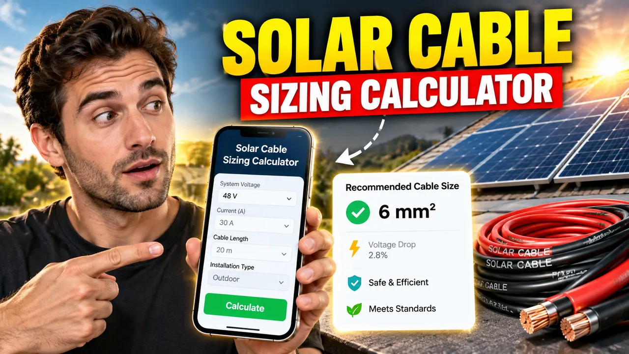
Solar Cable Sizing Calculator App
TL;DR Summary
The Solar Cable Sizing Calculator App estimates the conductor cross-sectional area needed for a DC solar cable run based on system voltage, operating current, one-way cable length, conductor material, and a selected voltage-drop target. It is a preliminary voltage-drop sizing tool, not a complete NEC conductor-compliance calculation, and no specific privacy behavior beyond the calculator inputs and outputs is assumed.
What the Solar Cable Sizing Calculator App Does
The Solar Cable Sizing Calculator App helps you estimate a suitable cable size for a solar photovoltaic DC circuit. Cable size matters because electrical resistance increases voltage loss as current travels through a conductor. A cable that is too small for the distance and current can produce more voltage drop than your design allows.
This tool focuses on the voltage-drop part of solar cable sizing. It uses the system voltage, expected operating current, one-way cable length, conductor material, and your maximum voltage-drop target. From those values, it estimates the minimum conductor area in square millimeters and then selects the next available size from a predefined standard-size list. It also gives an approximate U.S. AWG or kcmil equivalent where a useful comparison is available.
The tool is intended for people doing preliminary solar system planning, including homeowners, solar installers, electricians, designers, students, and technicians who need a quick starting point before completing a full electrical design. The result can help you see how cable length, current, voltage, and conductor material affect the required conductor area.
Inputs You Need
- System voltage: Enter the nominal DC voltage of the solar circuit in volts.
- Operating current: Enter the expected current carried by the cable in amperes.
- One-way cable length: Enter the physical cable route from the source to the load in feet. The calculation automatically accounts for both conductors in the DC circuit.
- Conductor material: Choose copper or aluminum. The material changes the resistance used in the voltage-drop calculation.
- Maximum voltage drop: Enter the percentage you want to use as your design target. The default is 3%.
These inputs reflect the basic factors that affect PV wire sizing. The U.S. Department of Energy notes that PV wire sizing depends on current, distance, voltage, temperature, and wire type. :contentReference[oaicite:0]{index=0}
How to Use
- Step 1: Enter the nominal DC system voltage for the solar circuit.
- Step 2: Enter the expected operating current in amperes rather than the physical cable's size.
- Step 3: Enter the one-way cable route length in feet.
- Step 4: Select copper or aluminum as the conductor material.
- Step 5: Enter the maximum voltage-drop percentage you want to allow for the cable run.
- Step 6: Review the calculated conductor area, recommended standard size, approximate AWG equivalent, estimated voltage drop, and estimated voltage at the load end.
- Step 7: Before installation, complete the separate ampacity, temperature, adjustment, overcurrent-protection, conductor-listing, wiring-method, grounding, and local-code checks that apply to the actual PV installation.
Technical Explanation and Formula
The calculator uses the standard preliminary DC voltage-drop relationship for a two-conductor circuit:
A = (2 × L × I × ρ) / Vd
- A = required conductor cross-sectional area in mm².
- L = one-way cable length in meters.
- I = operating current in amperes.
- ρ = conductor resistivity in ohm·mm²/m.
- Vd = permitted voltage drop in volts.
The tool converts the entered cable length from feet to meters. It calculates the permitted voltage drop from the system voltage and the selected percentage:
Vd = System Voltage × (Voltage Drop % ÷ 100)
The calculation uses approximate resistivity values of 0.0175 ohm·mm²/m for copper and 0.0282 ohm·mm²/m for aluminum. These values are used for a preliminary calculation rather than as a substitute for the resistance data of a specific cable at its operating temperature.
The factor of 2 accounts for the two conductors in a simple DC positive-and-negative circuit. After the required area is calculated, the calculator rounds upward to the next size in its standard-size list. Rounding upward helps ensure that the selected standard size is not smaller than the calculated voltage-drop area.
Worked Example
Suppose a 48 V DC solar circuit carries 20 A over a 100-foot one-way copper cable run, and the design target is 3% voltage drop.
The allowed voltage drop is:
48 V × 0.03 = 1.44 V
Converting 100 feet to meters gives about 30.48 meters. Using the copper resistivity value, the calculated minimum area is about 14.82 mm². The calculator therefore moves up to the next listed standard size, 16 mm², which has an approximate 6 AWG equivalent.
Using the selected 16 mm² size, the estimated voltage drop is about 1.33 V, or about 2.78%. The estimated voltage at the load end is about 46.67 V.
| Example input | Value |
|---|---|
| System voltage | 48 V DC |
| Operating current | 20 A |
| One-way length | 100 ft |
| Material | Copper |
| Voltage-drop target | 3% |
| Calculated minimum area | 14.82 mm² |
| Selected standard size | 16 mm² |
| Approximate AWG equivalent | 6 AWG |
| Estimated voltage drop | 1.33 V / 2.78% |
Why Cable Length and Voltage Matter
A longer cable run generally creates more voltage drop because the current travels through more conductor resistance. Higher system voltage can reduce the percentage impact of the same voltage loss because the voltage-drop value is divided by the system voltage when calculating the percentage. The U.S. Department of Energy likewise identifies current, distance, voltage, temperature, and wire type as important factors in PV wire sizing. :contentReference[oaicite:1]{index=1}
Why Use This Solar Cable Sizing Calculator App & How Our Calculator Beats the Competition
| Method | Ease of Use | Calculation Speed | Best For | Limitations |
|---|---|---|---|---|
| Toolhox Solar Cable Sizing Calculator App | Enter five focused inputs | Immediate calculation | Preliminary DC voltage-drop sizing | Does not replace a complete code and installation review |
| Manual Calculation | Requires formula work and unit conversion | Depends on the user | Learning and design verification | More opportunity for arithmetic or unit errors |
| Spreadsheet | Requires a prepared worksheet | Fast after setup | Repeated project calculations | Formula setup and maintenance are required |
| Professional Engineering Software | Usually requires more setup | Depends on the software and model | Detailed electrical design | More inputs and engineering decisions may be required |
Important U.S. Solar and NEC Context
NFPA identifies the 2026 edition of NFPA 70, the National Electrical Code, as the current edition. PV conductor requirements are installation-specific. NEC Article 690 addresses photovoltaic systems, and PV conductor ampacity rules are separate from a simple voltage-drop calculation. The 2026 NEC also contains specific provisions for PV conductors and their ampacity. :contentReference[oaicite:2]{index=2}
PV cable selection also involves the cable's listing and suitability for the installation. UL Solutions identifies UL 4703 as the standard for photovoltaic wire and describes PV cables as subject to applicable North American certification requirements. :contentReference[oaicite:3]{index=3}
Assumptions and Limitations
- This is a preliminary DC voltage-drop sizing calculation.
- The calculation assumes a simple two-conductor DC circuit and uses twice the one-way length for the electrical path.
- The calculator uses approximate conductor resistivity values rather than the exact resistance specification for a particular cable.
- Temperature-related resistance changes are not modeled directly.
- The calculation does not independently determine NEC ampacity, temperature correction, adjustment factors, conduit fill, OCPD rating, equipment-terminal limits, grounding-conductor sizing, conductor insulation requirements, or cable listing.
- The calculator does not determine whether a particular PV cable is permitted for a specific outdoor, wet, raceway, rooftop, direct-burial, or other installation condition.
- Actual PV installation requirements can depend on the adopted NEC edition, local amendments, equipment instructions, wiring method, environmental conditions, and the Authority Having Jurisdiction.
- A voltage-drop target such as 3% should not be treated as a universal code limit. Applicable requirements must be checked for the actual circuit and jurisdiction.
DOE guidance emphasizes that properly sizing PV wiring is an important safety and system-design consideration and that wire type, temperature, current, voltage, and distance all matter. :contentReference[oaicite:4]{index=4} DOE also highlights the importance of appropriate PV cable management and protection from environmental exposure. :contentReference[oaicite:5]{index=5}
Use the result as a starting point for design or discussion. For a permitted or safety-critical installation, have the complete conductor selection reviewed against the applicable electrical code, equipment documentation, and local requirem:contentReference[oaicite:6]{index=6}:contentReference[oaicite:7]{index=7}